
|
|
Hypercube 100A Dual H-Bridge Board 2018-11-09 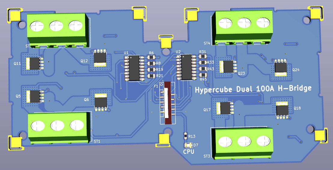
History
Uses - This board useful for making high end 3D printers with big motors
- With modern fast ARM CPUs, it can be used in phase shifted bridge operating mode for highest efficiency
- Drive MPDWE (a motor that has no axle for heavy lift drones and cars with floating wheels that may travel around 4x speed of sound in an evacuated tunnel)
- Control high power drone motors for heavy lift and drone delivery
- Make 3D metal printer
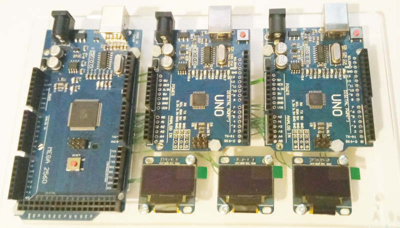
- Can be paralleled up to drive car motors and electric vehicles and develop the drive train more quickly. The inputs to the H-Bridge are simple 3.3V and can be driven by 3.3V Arduino boards and ARM SoC boards.
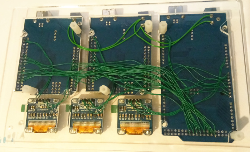
- One board in total can handle 200A at 25V i.e. about 5kW. 12 boards in one fully formed Hypercube can handle 60kW. 60kW more than good enough for make electric bikes, and electric cars.
- 10 fully populated Hypercubes of 100A Dual H-Bridge boards can potentially drive a lorry, bus, coach etc with 700kW motor
- One fully populated Hypercube is enough to drive the most powerful humanoid sized 3D printed walking robots. (Something we hope to be making soon.)
- H-Bridge max voltage is 30V - which is ideal for 24V battery systems
- The GND is common between the motor supply for safety.
- The drive circuit is optically isolated to prevent high dV/dt and dI/dt signals reaching the 3.3V CPU
- However the CPU should be protected with metal grounded shielding otherwise extremely powerful EMP signals will reach the CPU and knock it out when switching around 5kW of energy.
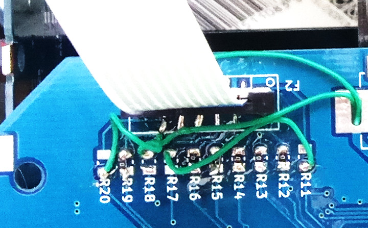
- The input lines are held low by pull down resistors.
- Sending a 3.3V high signal will turn on the appropriate H-bridge MOSFETs
- The design is arranged as 4 half H-bridges. This allows the half bridges to be paralleled to make extremely high current H-bridge.
- The half bridges are wired manually to make full bridges. The contact rating of the screw terminal is 20A. If more current needed, the solder pads to the connectors have been made large allowing bigger wires to be soldered directly to the board. The wires can be soldered direct to the leads of the MOSFETs - but take care, as it definitely invalidates any warranty as well as damage a lot of things if 100A circuit is mis-wired.
2018-06-28 
2018-06-29 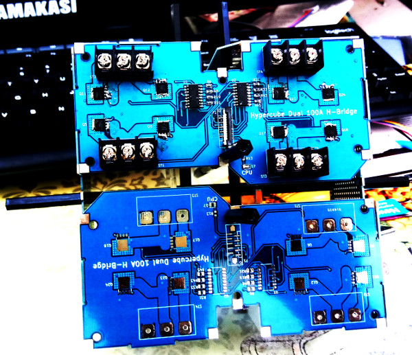
2018-06-29 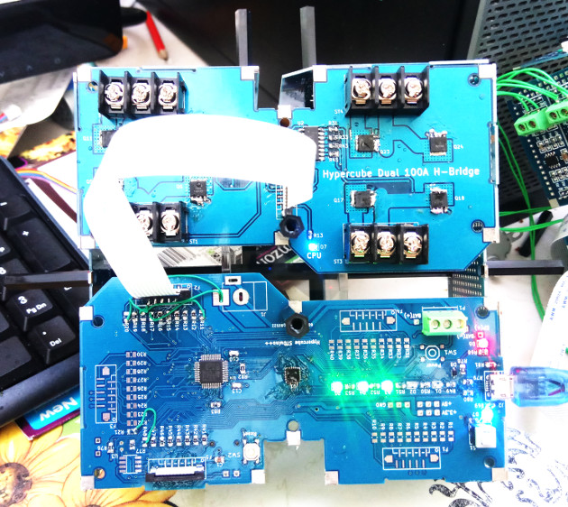
2018-06-30
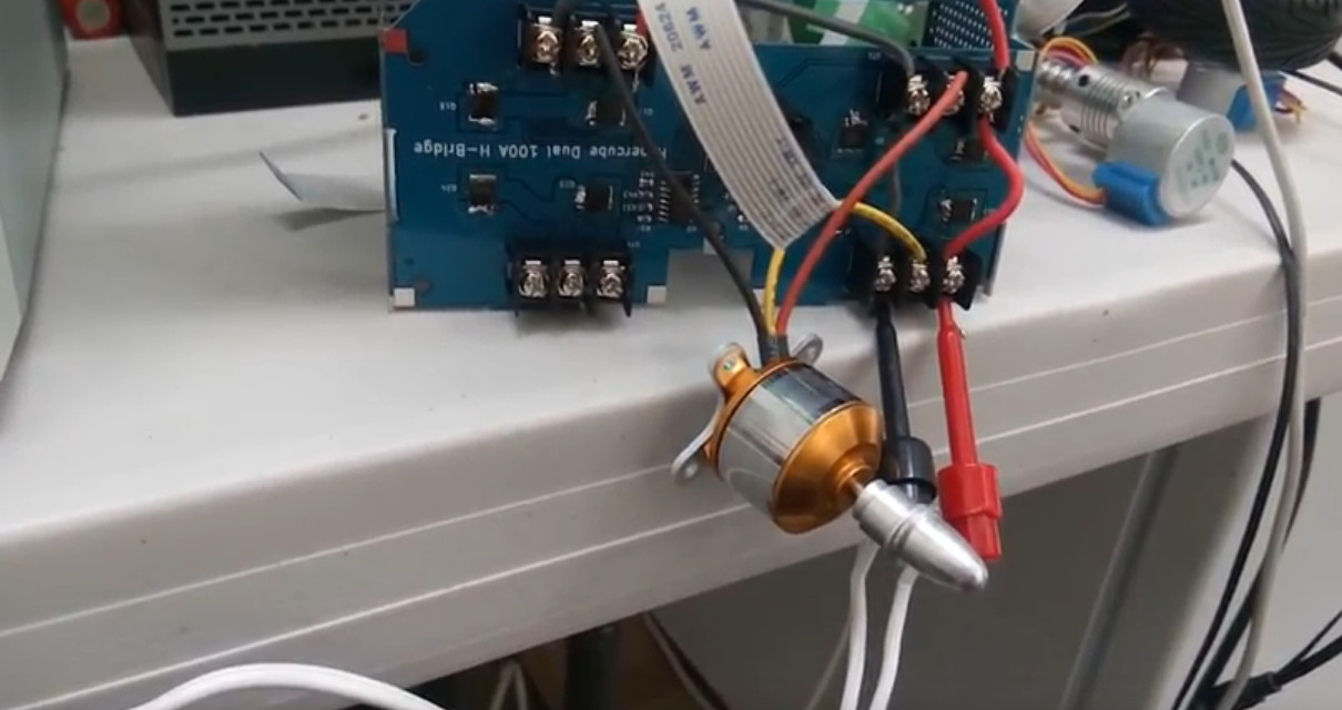
100A Dual Half-H-bridge configured as 3 phase BLDC motor driver
2018-07-18
|