|
Home Page
Six Transistor Cache
Investors
Launch Date
Contacts
Terms and Conditions
_________________________
|
Hypercube Developer Website
Hypercube USB Powered Breadboard 
2018-11-08
- This is final version before release of USB powered breadboard
- This has added power mixer so it can operate from solar as well as mains powered DC socket
- Plus a number of other small tweaks to make it more friendly to use gained from practical use cases
Older Information
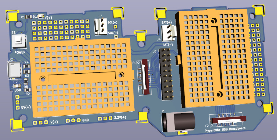
- The board has two breadboards and option to be powered up USB or a 2.1mm DC jack socket
- If powered by USB, the board will have 5V and 3.3V
- A pair of FPC connects signals to 2.54" spaced pins and these are wired with Dupont wire to the breadboard
- The FPC sockets are at right angles to each other to allow for FPC cables to come in from different directions.
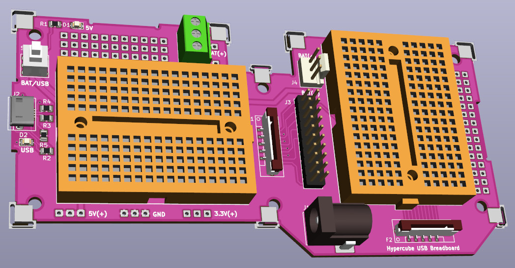
- Change the colour to be purple for variety
- Soon to be open sourced :)
- List of other boards to be open sourced
3D Model
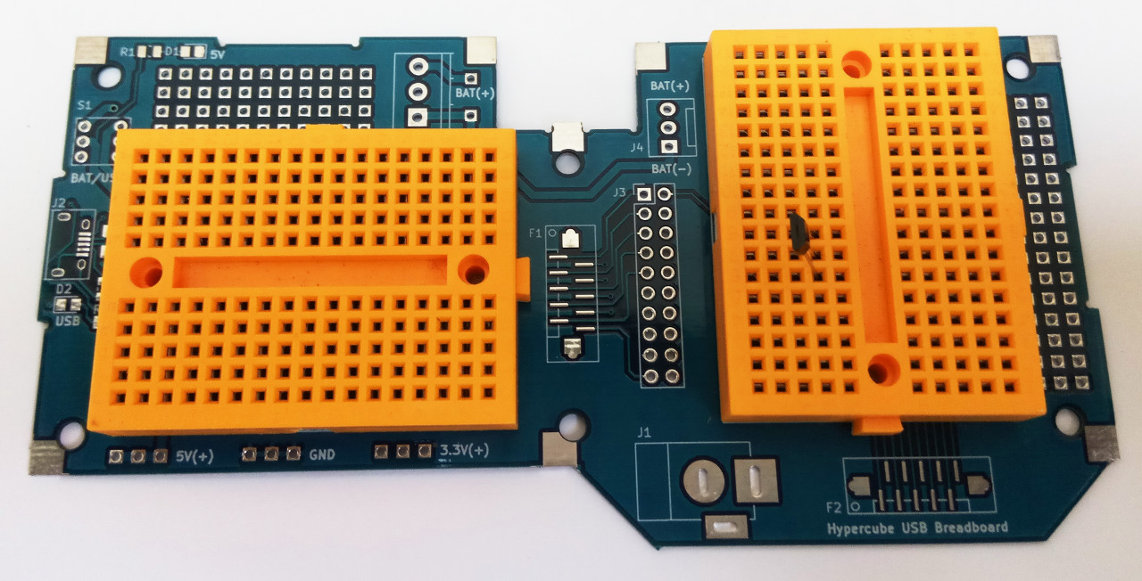
- Could not find an orange breadboard anywhere at the time, so make our own with LibreCAD for dxf files, OpenSCAD to construct 3D model and output in .CSG, and FreeCAD to convert the .CSG to step file :)
- The orange coloured breadboard 3D model design files and step file for KiCAD SY_170_breadboard_2018_05_28.tar.gz
- The board is now made as shown in above picture
- So far the board has the following features
- Hypercube compatible
- Two mini bread boards
- Two prototyping areas
- Two 10 FPC input/output connectors
- Works from 5V DC jack
- Can use micro USB power to generate 5V and 3.3V power to the breadboards if running from USB
- A DPDT latching switch to power on and off the circuit
- Can run from batteries with screw terminals or 0.1" header F-lock connector for battery input
- Large GND planes under the breadboard to make signal integrity better
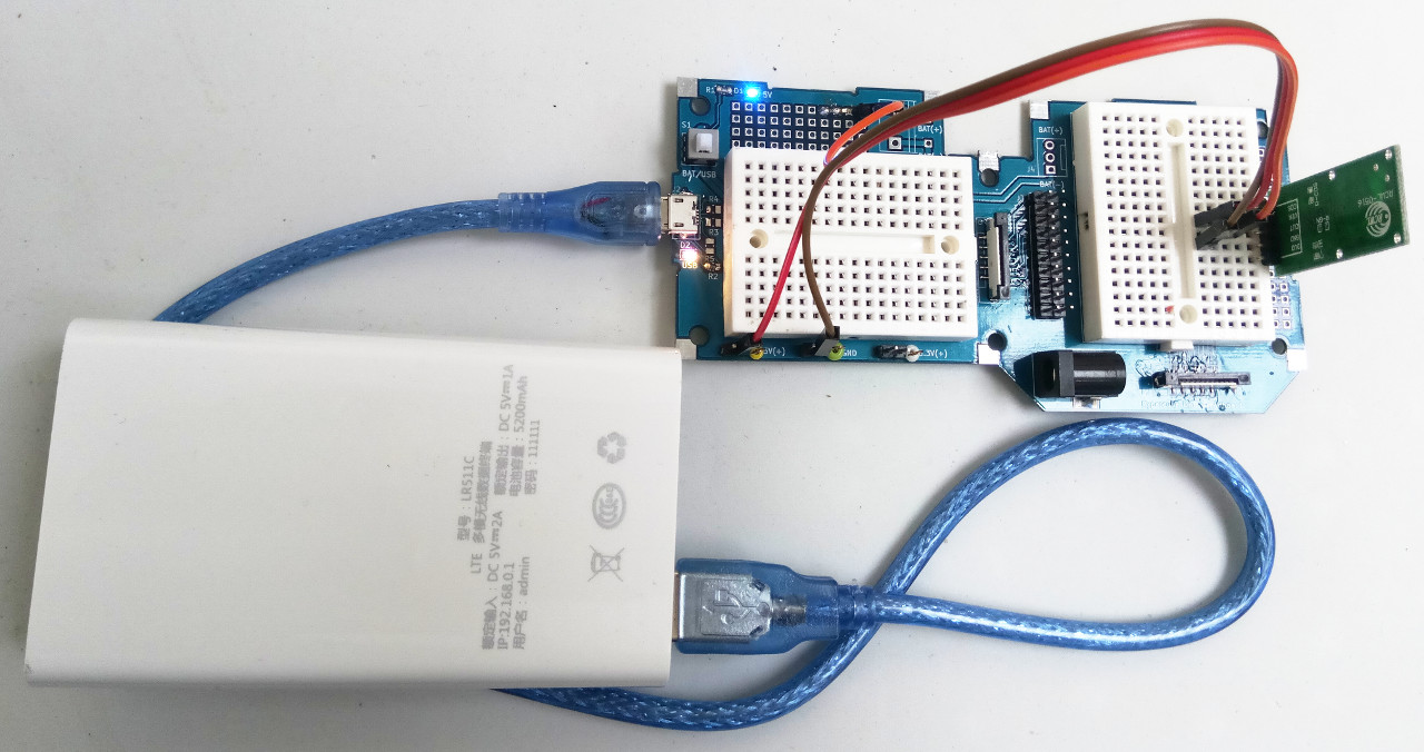
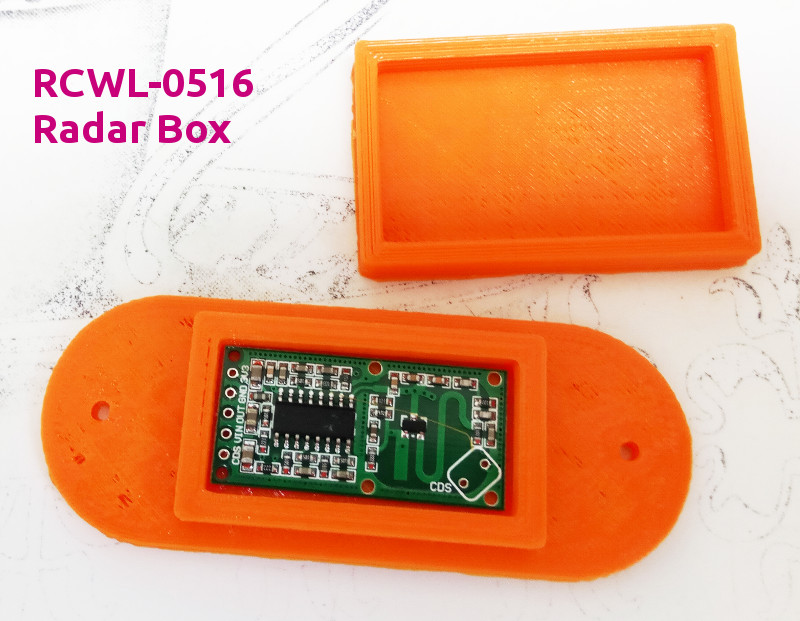
Example use of USB Breadboard - RCWL-0516 Module
- A prototype made from RCWL-0516 Radar module that detects people movement, and also metallic objects like door opening tools operated near a door.
- The RCWL-0516 sensor works through glass and through obstructions such as thin (non metallic) walls.
- The unit is powered via micro USB connector from a battery bank commonly used with mobile phones.
- Some items (LED + resistor) soldered on the perforated hole PCB sections. Other wires connected by Dupont wires to breadboard.
- The output high voltage varies with power supply from about 2.5V to 3.3V
PCB Dimensions - 36mm x 17mm module
- The circuit can be wired back to a CPU board through the FPC wires during prototyping work.
- NOTE - Breadboard is notoriously prone to disconnections during complex work. Once prototyping work finishes, transfer the work to perf board such as USB powered prototyping board
- Here is file for a 3D printed box for the radar module - RCWL0516_radar_box.tar.gz
- On a low definition 3D printer, the rough edges of these boxes allows the lid to snap fit. If you have a higher definition printer, lower the accuracy by using a bigger nozzle size, increase the extrusion magnifier for this print to something like 1.1 (to extrude more filament per layer) or use glue if the fit is not perfect.
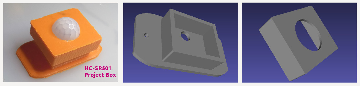
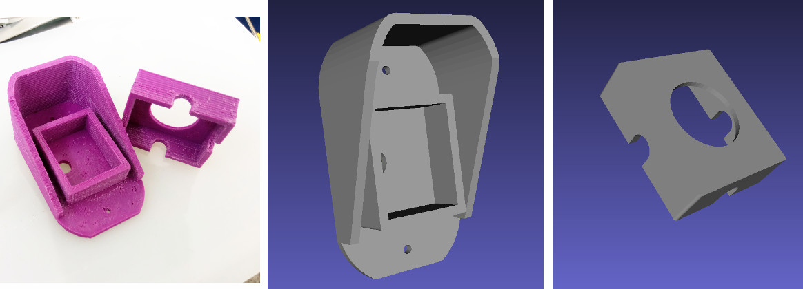
Example use of USB Breadboard - HC-SR501 Board
- Similar to radar board, a prototype was built from HC-SR501 PIR sensor board with USB Breadboard to check everything worked.
- Then a 3D printed case was made to house it.
- On a low definition 3D printer, the rough edges of these boxes allows the lid to snap fit. If you have a higher definition printer, lower the accuracy by using a bigger nozzle size, increase the extrusion magnifier for this print to something like 1.1 (to extrude more filament per layer) or use glue if the fit is not perfect.
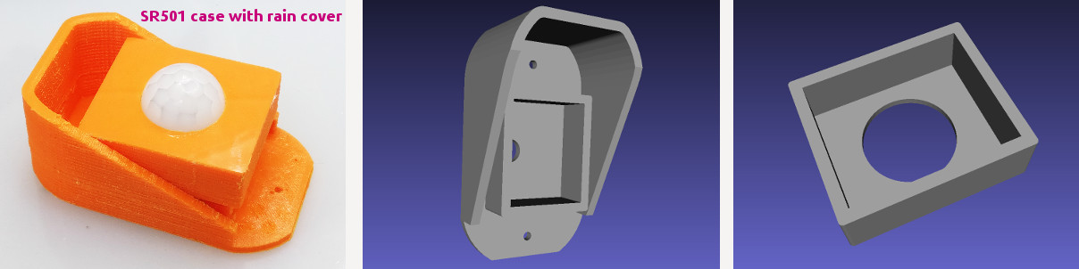
- Another version of the above case has a rain cover
- On a low definition 3D printer, the rough edges of these boxes allows the lid to snap fit. If you have a higher definition printer, lower the accuracy by using a bigger nozzle size, increase the extrusion magnifier for this print to something like 1.1 (to extrude more filament per layer) or use glue if the fit is not perfect.
- Another version of the above case with slots at the sides for cables
- The hole for the cable is drilled through the other walls of the case after the printing is finished. This gives better definition for a hole as vertical holes are difficult to make precisely
- The cap with the slot is also good for the first version of the case if running cables through the side of the detector.
- Most likely this kind of hole through the side of the case require silicon sealant to prevent rain and condensing moisture entering the case.
- On a low definition 3D printer, the rough edges of these boxes allows the lid to snap fit. If you have a higher definition printer, lower the accuracy by using a bigger nozzle size, or increase the extrusion magnifier for this print to something like 1.1 (to extrude more filament per layer) or use glue if the fit is not perfect.
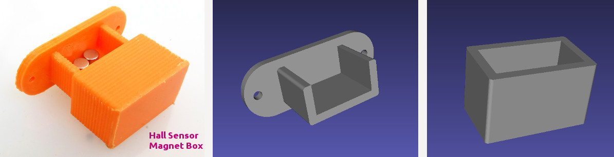
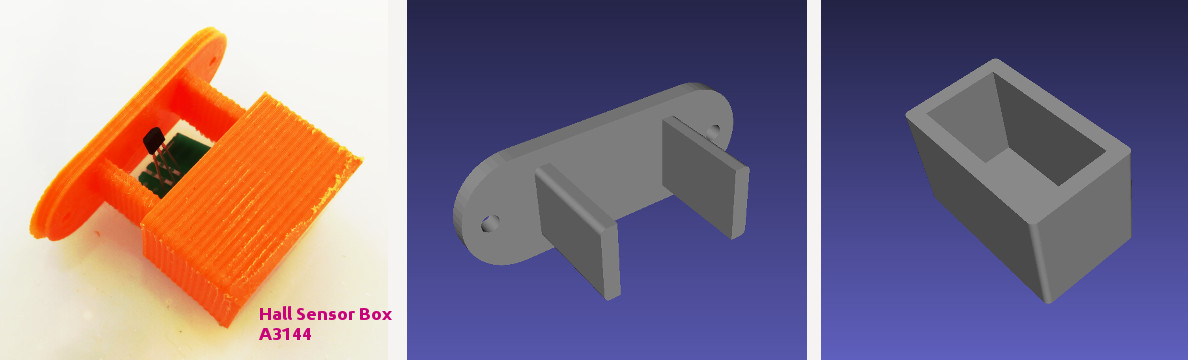
Example use of USB Breadboard - HC-A3144 Hall Sensor
- A3144 Hall sensor is useful for checking open doors in security applications
- Easy to prototype on USB Breadboard (which has 5V and 3.3V)
- It needs a magnet to be fitted to a door to operate it. So we make a magnet box for screwing on to door
- The 3D printable files are in this compressed file - Door_Magnet_Box.tar.gz
- Add padding material to the magnet to hold it in correct position before snapping shut the box
- Add padding material to hold the PCB and Hall sensor in correct orientation.
- A hole needs to be drilled into the lid to allow a cable to be passed from PCB to the CPU.
- For best Hall sensing effect, bend the A3144 flat onto the PCB, then a magnet pole is arranged to face the flat side of the A3144 chip, while behind the PCB a small piece of tin needs to be added (after insulating it with tape). If the Hall sensor is not switching, reverse the magnet polarity.
- On a low definition 3D printer, the rough edges of these boxes allows the lid to snap fit. If you have a higher definition printer, lower the accuracy by using a bigger nozzle size, increase the extrusion magnifier for this print to something like 1.1 (to extrude more filament per layer) or use glue if the fit is not perfect.
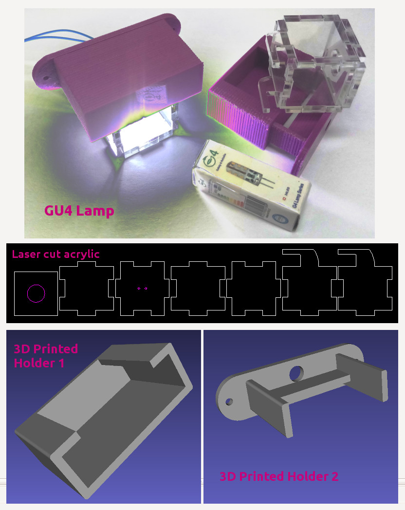
GU4 Lamp Holder
- The G4 12V lamp holder is made from 3D printed plastic and 3mm acrylic laser cut parts G4_lamp2b.tar.gz
- On a low definition 3D printer, the rough edges of these boxes allows the lid to snap fit. If you have a higher definition printer, lower the accuracy by using a bigger nozzle size, increase the extrusion magnifier for this print to something like 1.1 (to extrude more filament per layer) or use glue if the fit is not perfect.
- The circuit diagram for controlling the lamp is below:
- The purpose of adding the 1N4148 to the circuit is to be generic so that long inductive leads don't cause problems for the CPU
- The circuit can be used for generic loads such as electric locks, high power alarms and motors up to 3A without problems
- In a large and complex project, the purpose of R1 with value of 10K is to ensure that loads such as LEDs don't turn on in noisy environments. If the LEDs are flashing intermittently from noise, decrease R1 to about 1K. Also shield the wire that triggers the gate Q1 from the noise.
|