|
Home Page
Six Transistor Cache
Investors
Launch Date
Contacts
Terms and Conditions
_________________________
|
Li-Fi on Hypercube Boards
- Hypercubes will sport Li-Fi circuits. Li-Fi means Light Fidelity. The Tx and Rx devices mounted near the conduit hole on opposing Hypercubes will allow Hypercubes to communicate over a low speed channel.
- Some detail here for circuit designs - all open source
- While good quality lasers provide GHz and THz line of sight communications inside a Hypercube Array, it is also possible to implement slow speed Li-Fi communications using LEDs and solar cell receivers.
- There are three pairs of conduit holes in a Hypercube when fully assembled.
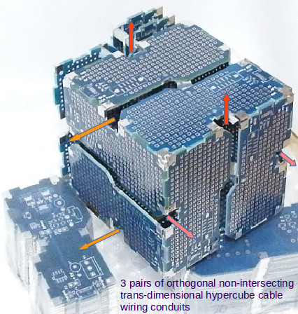
- Each pair is non-intersecting. One of those conduits could carry signal wires and power wires while the second can carry low power class 2 laser beams that propagate from one end of the Hypercube array all the way to the other end of an array. If the space is split, potentially hundreds of parallel THz beams can be carried within large conduit spaces of Hypercube Data Center systems. If the spacing of the beam is 1mm separated by 1mm gap, then it would be possible to insert a 1mm square mirror into the parallel beam array with an actuator and communicate directly between cubes when needed.
- There is a solder tag in the conduit to solder conduit PCBs. The conduit PCBs are designed to carry laser(s) and detector(s) as well as displays, LED strips, speakers, sensors etc.
- Another source of high speed lasers and photo detectors are SFP modules used in fiber optic communications. Currently gigabit SFP modules are about $14 in Aliexpress.
- Class2 lasers are about 1mW, used in pointers, are safe if accidentally enter the eye, but SFP module lasers can be higher, so as always, never look directly into a laser when building laser communications links.
- With use of lasers, 3D wired Hypercube arrays would never be short of bandwidth to get signals in and out of the array.
- With Li-Fi, the intention is to provide a mesh like network of connection channels for low speed data typical of IoT devices.
- The expected speeds are 1Mbit although 100Mbit and 100kbit are possible - depending on the effort made.
- It would be better if dedicated chips are available for Li-Fi, but the technology is still in its infancy.
- So we support Li-Fi development by designing the circuits and implementing the protocols needed of IoT use of Li-Fi.
- We describe here how to make Li-Fi without complex circuits and protocols using simple LEDs and solar cells.
Li-Fi Circuits and Speeds
- A simple LED can emitt GHz radiation, and solar panels can detect GHz radiation.
- The reason is that light emission is extremely sensitive to power input to the LED and same applies to solar cells which are extremely sensitive to amount of light received.
- The circuits to modulate LED to GHz and amplify GHz solar cell signals gets complex as the speeds go up, but to make a start, we do simple designs until we can get hold of cheaper solutions.
- The LED (or LED laser diode module - with internal capacitors removed) is always lit through current flowing in R1 and low resistance transformer winding of T1.
- By applying a differential signal to the primary of T1, the current reaching the LED is modulated.
- We can connect LED to a transistor and switch it - but it becomes difficult as the LED power ramps up.
- The LED can be 10W, 100W, or milliWatt LEDs or real LED lasers. The transformer needs to be adjusted accordingly to allow greater power.
- For small SMT LED and small DIP LEDs, simple Ethernet transformer toroids may work. Those can be pulsed at GHz speeds.
- Buying a toroid ring and winding your own transformer is an option for higher power LEDs.
- The ratio of primary to secondary should be about 1, but can be adjusted to a bigger number for greater modulation.
- The receiver can be the same identical Red LED (which behave like photo diode) for best spectral matching (avoid using different color LEDs!). Alternatively, they can simple solar cells or photo diodes.
- The photo diodes need to be bunched together if several of them are strung into a series. They can be paralleled to catch light from different angles.
- The photo diode current feeds into a Darlington pair in the form of Q1 and Q2. Any slight fluctuation of the current through R4 and Q2 is coupled via capacitor C1 to the opamp which amplifies the signal.
- A good op-amp will push the output signal to MHz. Otherwise the output is in the KHz region. The gain resistors Ra and Rb are set for best gain before noise overwhelms the op-amp.
- Typically the noise in the signal between the (+) and (-) input of op-amp needs to be below 2mV.
- If you manage to get low noise results, then use better op-amps with higher frequency response. Adding and FPGA for data signal processing would be the next step, but by that stage, the costs have gone up and power requirements have gone up. All screaming for a dedicated chip to be designed! If you have what it takes, you can design the chip, and send it through MOSIS system to get custom chips made at low cost.
- The present configuration connects the photocells through D2 to the 5V rail through R2.
- R2 needs to be much higher (e.g. 100K) if the photo diodes are sensitive.
- The photo diode D2 can instead be connected to GND without resistor R2.
- That would then rely on enough light reaching photo diodes to turn them on and generate enough current to drive Q1 and Q2. That is possible if the photo diodes are facing each other at close distance. (Each photo diode connections need to be reversed if connecting to GND.)
- R3 and R5 are to reduce noise and can be removed if noise is negligible.
Dark Li-FiTM
- Our investor Dilead and its engineers are developing 'Dark Li-Fi' TM a form of Li-Fi which has Optical LED such as white LED (which may or may not be modulated), and parallel IR signals which are invisible.
- The idea of Dark Li-Fi is that the light can be off, but light based communications using IR range can still continue in the dark.
|