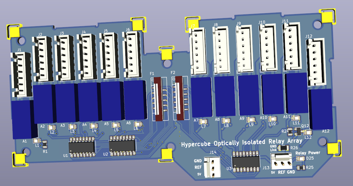
Hypercube Optically Isolated Relay Array Board
2018-11-12
- This is final revision of the relay board before launch.
- This board has 12 optically isolated relays.
- Each relay is DPDT relay allowing a pair of signals to be toggled at the same time.
- Potentially for IoT devices (with low speed communications requirements) this relay board can switch 12 RS485 busses to one single CPU.
- Each RS485 can carry 63 low speed devices making this relay board able to multiplex up to 12 x 63 devices to a single CPU to control.
History
- Design work finished - done up in KiCAD.
- Designed to shut down and/or reboot Hypercube CPU boards in Hypercube arrays without having to down the entire system.
- This kind of board easily used to build redundancy based computing.
- As systems grow larger, you may add a lot of boards to the Hypercube array such as Arduino clone boards, stepper driver array, lithium charger arrays etc and sometimes you want to reboot boards, sometimes power them down, and sometimes power them up when needed.
- The entire system is reconfigurable on the fly with the use of relays to deliver power to specific boards as needed.
- Up to 12 boards can be independently controlled with 12 independent DPDT relays. If paralleling up boards, then up to 2A can be drawn from each relay to power multiple boards.
- In a fully populated Hypercube with relay array boards, a total of 144 power lines can turned on or off. This makes for a huge amount of control and suited to controlling a large number of items in a machine, around the office, or around a house with numerous IoT devices to control.
- It is suitable for building your own custom compact ATEs (Automatic Test Equipment) that require a large number of relays to route signals from boards under test in a bed of nails to measuring devices. Typically they are used to check boards coming off the production line for faults, and prevent burn outs if there are short circuits and open circuits in the newly soldered board. They are also used for calibration by applying various calibrated loads and then triggering calibration buttons. Real calibrators are expensive and can get damaged if there is a fault in your new board, so you can design custom ATEs with less accurate resistors to check initial automated calibrations will pass OK before handing the work over to be carried out with a professional calibrator.
- The relays are optically isolated so that it can be operated with the CPU disconnected from any high energy power sources that drives the relays.
- All soon to be open sourced so you design your own boards and/or remix as much as you want.
- We will release with it good quality open source multi-tasking software to handle hundreds of relays.